Introduction

OSPF (Open Shortest Path First) is a routing protocol used to distribute routing information within a single autonomous system (AS). OSPF is an open standard protocol that is widely used in large enterprise networks due to its scalability and fast convergence times. OSPF uses a hierarchical network structure, with routers grouped into areas, each with its own designated router (DR) and backup designated router (BDR). This structure helps to reduce the amount of routing traffic and improve the efficiency of the network. The OSPF protocol exchanges routing information between routers using link-state advertisements (LSAs), which are packets that contain information about the state of the router's links. Each router maintains a database of link states (LSDB) of all the LSAs it has received from other routers in the network. OSPF uses a metric called "cost" to calculate the shortest path between two routers. The cost is based on the bandwidth of the link, with higher bandwidth links having a lower cost. OSPF uses the Dijkstra algorithm to calculate the shortest path between two routers based on the cost. One of the benefits of OSPF is its ability to support unequal cost load balancing, which allows traffic to be distributed across multiple paths with different costs. OSPF also provides support for authentication and route summarization, which helps to reduce the amount of routing information in the network.

Description
OSPF is a link state routing protocol - it uses the current state of links for routing decisions
OSPF uses a hierarchical network structure, with routers grouped into areas
Each area has its own designated router (DR) and backup designated router (BDR)
The designated router (DR) is responsible for sending and receiving OSPF messages on behalf of all other routers
The DR is elected by the routers on the network segment by the router's priority and router ID
Once a DR is elected, it becomes the central point of communication for all routers on the network segment
The backup designated router (BDR) is the router with the second-highest priority on the network segment and is responsible for taking over as the DR if the current DR fails
This structure helps to reduce the amount of routing traffic and improve the efficiency of the network
The OSPF protocol exchanges routing information between routers using link-state advertisements (LSAs)
LSA packets contain information about the state of the router's links
Each router maintains a database of link states (LSDB) of all the LSAs it has received from other routers in the network
The link state database is formed by the collection of all link states in the topology
OSPF uses a metric called "cost" to calculate the shortest path between two routers
The cost is based on the bandwidth of the link
Higher bandwidth links have a lower cost
OSPF uses the Dijkstra algorithm to calculate the shortest path between two routers based on the cost
OSPF also provides support for authentication and route summarization
OSPF routers send "hello" messages & neighboring OSPF routers establish neighbor adjancencies
Description
Routers form neighbor relationships via the multicast address 224.0.0.5, link local multicast 224.0.0.6, or unicast
Routers send LSAs to advertise the state of links every 30 minutes by default or as soon as states change
OSPF does not use TCP or UDP - it is a OSI layer 3 protocol and resides in the IP header (protocol ID 89)
All OSPF routers share the same database - all have the same topology map
It is also a interior gateway protocols (IGP) - IGPs are used within an autonomous system (AS)
Other interrior gateway protocols are for example RIP & EIGRP
OSPF can be segmented into multiple different OSPF areas
Area 0 is always the default area for OSPF to start from - it is the "backbone area"
The traffic between other areas traverse the backbone area 0
The backbone area 0 can also be represented as area 0.0.0.0, depending on the system
Cisco recommended not to use more than 50 routers in one area
Large OSPF networks can be segmented into multiple areas to keep LSA messages within the areas
Area border routers (ABR) are located between the backbone area 0 and another area
ABRs have one interface in the area and another interface in another area
ABRs allow the summarization of routes
An ASBR (autonomous system border router) is are located between two different autonomous systems (AS)
Passive Interfaces prevent OSPF from sending Hello packets and LSAs (Link State Advertisements) - this is used for interfaces that are connected to end-user devices or other AS networks

OSPF Router Types

OSPF uses multiple router types to maintain the OSPF process:

Router Types
Designated Router (DR)
Backup Designated Router (BDR)
Area Border Router (ABR)
Autonomous System Border Router (ASBR)
Backbone Router
Internal Router
Description
The DR is elected by the highest priority, interface IP or router ID - the DR is responsible for sending and receiving OSPF messages on behalf of all other routers
The BDR has the second-highest priority and is responsible for taking over as the DR if the current DR fails
ABRs reside between different OSPF areas, this allows route summarization
ASBRs reside between different autonomous systems (AS)
Backbone routers reside inside the backbone area 0 and only have interfaces within this area
Internal routers reside inside their specific areas and have all interfaces within their area

The DR is elected by the highest priority, highest router ID or the highest available interface IP address, depending on which information is available for the OSPF election process. The second router in that list becomes the BDR. If no priority and no router ID has been configured, the process searches for the highest interface IP address it can find and elects that router as DR and the router with the second highest IP address available as the BDR. It is recommended  to use priority & router ID to determine DR & BDR when planning a OSPF network. DR & BDR are best used in broadcast multi access environments.

Election
1. Higher priority
2. Higher router ID
3. Any higher interface IP address
Info
1-255 / 1=default / 0=never become DR
###.###.###.###
###.###.###.###

If a change in the network occurs, the corresponding router sends an update only to the DR. The DR listens to the multicast address 224.0.0.6. The DR then informs all other routers in the area via the multicast address 224.0.0.5. All other routers listen to the multicast address 224.0.0.5. If the DR fails, and comes back online, no new election starts. The former DR will not become the designated router again. The current DR keeps the DR role. the OSPF election process is not preemptive.
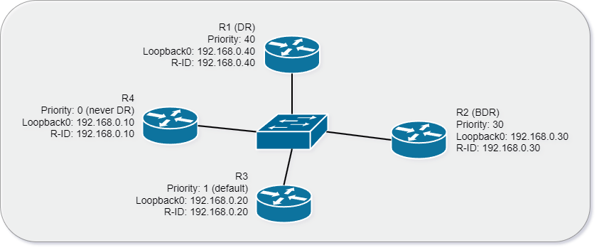
The topology above shows a OSPF broadcast multi access environment.

OSPF Tables

OSPF routers use tables that contain information to maintain the OSPF process:

IP OSPF Neighbor Table (Adjacency Table)
The adjacency table is a data structure that contains information about the OSPF neighbors of a router
IP OSPF Topology Table (LSDB)
The LSDB stores information about the network topology as discovered by OSPF routers - it contains all routers & connected links in the network area
IP Routing Table (Forwarding Table)
The routing table stores information about the best path to reach each destination network (the best routes)

OSPF Packet Types

Routers exchange mulitple different packets types to maintain the OSPF process:

Packet Types
Hello Packets
-
-
-
-
Database Description Packet (DD/DBD)
Link State Request (LSR)
Link State Update (LSU)
Link State Acknowledgements (LSAck)
Description
Hello Packets are used to dynamically discover neighbors
They are also used to form and maintain neighbor relationships
The default intervall is 10 seconds on broadcast segments
On non-broadcast segments (serial links, NBMA) the intervall is 30 seconds
The dead timer is 4x the hello timer by default
Database Description Packets are used to exchange brief versions of LSAs
LSRs are used to request the full LSA information from a neighbor
LSUs are used to response to LSRs and contain LSAs
LSAck Packets are used to confirm the receipt of an LSU message

Hello packets are sent via the multicast address 224.0.0.5. They contain the following information:

Hello Packet
Router ID
Hello and dead intervals
Neighbors
Area ID
Router Priority
Designated Router (DR) IP address
Backup Designated Router (BDR) IP address
Authentication password
Stub area flag

LSA Types

A Link State Advertisement is a packet that contains information about the state of a link or a router in a link-state routing protocol. There are several types of LSAs, which carry different types of information, and are used for different purposes in a network.

LSA Types
Type 1 - Router Link: Type 1 link state advertisements are distributed within an area - it lists router neighbors and the cost to reach them
Type 2 - Network Link: Type 2 link state advertisements are generated by a designated router (DR), and are distributed within an area - it lists all routers on a segment
Type 3 - Network Summary: Type 3 link state advertisements are advertised among areas, and they are generated by an area border router (ABR)
Type 4 - ASBR Summary: Type 4 link state advertisements are injected by an area border router (ABR) into the backbone to advertise the presence of an autonomous system border router (ASBR) within an area
Type 5 - External Link: Type 5 link state advertisements are generated by an autonomous system border router (ASBR), and distributed in the autonomous system (AS) to advertise a route external to OSPF
Type 7 - NSSA External Link: Type 7 link state advertisements are generated by an autonomous system border router (ASBR) in a not-so-stubby area - the type 7 LSA will be converted into a type 5 LSA by the area border router (ABR) when it leaves the area

Area Types

In OSPF, a stub area is an area in which certain types of external routes are not propagated. This can help reduce the amount of OSPF traffic and improve network performance. There are several different types of stub areas in OSPF:

Area Types
Standard Area: This is the default OSPF area
Stub Area: All external routes (Type 5 LSAs) are replaced with a default route (Type 3 LSA). This default route is propagated throughout the stub area, and all traffic destined for external networks is forwarded to this default route. Standard stub areas are useful for reducing the amount of routing information in the network and improving performance.
Totally Stubby Area: External routes are replaced with a default route, and also all Type 3 and Type 4 LSAs are suppressed. This means that routers within the area only have information about directly connected networks and the default route. Totally stubby areas are typically used in smaller networks where reducing the amount of routing information is critical.
Not-So-Stubby Area (NSSA): NSSAs are designed to support the redistribution of external routes into OSPF, while still maintaining the benefits of a stub area. In an NSSA, Type 5 LSAs are converted to Type 7 LSAs, which are then propagated throughout the area. A Type 7 LSA is then translated to a Type 5 LSA at the NSSA border router, which is then propagated throughout the OSPF domain.
Totally Not-So-Stubby Area (T-NSSA): Similar to a totally stubby area, a T-NSSA suppresses all Type 3 and Type 4 LSAs, but still allows external routes to be redistributed into OSPF. In a T-NSSA, Type 5 LSAs are converted to Type 7 LSAs, and a default route is propagated throughout the area. At the T-NSSA border router, Type 7 LSAs are translated to Type 5 LSAs and are then propagated throughout the OSPF domain.
Area Types
Stubby
Totally Stubby (TS)
Not-so-Stubby Area (NSSA)
Totally NSSA
Stop Injection of Type 4/5 LSAs
Yes
Yes
Yes
Yes
Stop Injection of Type 3 LSAs
No
Yes
No
Yes
Allow Creation of Type 7 in the Area
No
No
Yes
Yes
LSAs
Stub Area (Stubby Area): Filters LSA 4 & 5, contains LSA 1, 2 & 3
Totally Stub Area: Filters LSA 3, 4 & 5, contains LSA 1, 2 + (type-3 default route)
Not-So-Stubby Area (NSSA): filters LSA 4 & 5, contains LSA 1, 2 & 3 and creates LSA-7
Totally NSSA: Filters LSA 3, 4 & 5, contains LSA 1, 2 and creates LSA-7+ (type-3 default route)

Network Types

Each OSPF network type has its own characteristics and considerations in terms of neighbor discovery, adjacency formation, and routing information exchange. The choice of OSPF network type depends on the underlying network topology and requirements of the OSPF deployment.

Network Types
Point-to-Point (P2P): In a point-to-point network, there is a direct link between two OSPF routers. This network type is typically used for connecting two routers together, such as in a leased line or dedicated link scenario. In a point-to-point network, OSPF routers form a neighbor adjacency with each other, and OSPF Hello packets are exchanged to establish and maintain the adjacency. Each router treats the other router as its neighbor and exchanges OSPF routing updates.
Broadcast: A broadcast network is a multi-access network where multiple OSPF routers are connected through a shared medium, such as Ethernet. In a broadcast network, OSPF routers use OSPF Hello packets to discover and form adjacencies with neighboring routers. The OSPF Designated Router (DR) and Backup Designated Router (BDR) are elected to reduce the amount of OSPF traffic on the network. OSPF routers exchange routing updates with the DR and BDR, and the DR distributes the updates to all other routers on the network.
Non-Broadcast Multi-Access (NBMA): Non-broadcast multi-access networks are similar to broadcast networks in that they are multi-access networks without automatic neighbor discovery. However, unlike broadcast networks, OSPF routers in an NBMA network do not have a shared medium or automatic flooding of OSPF packets. Examples of NBMA networks include Frame Relay and ATM networks. In an NBMA network, OSPF routers must be manually configured with the list of neighbors, and OSPF Hello packets are used to establish and maintain neighbor adjacencies. In the absence of a shared medium, OSPF packets are unicast between neighbors.
Point-to-Multipoint (P2MP): A point-to-multipoint network is a network where a single OSPF router connects to multiple OSPF routers in a hub-and-spoke topology. The hub router establishes neighbor adjacencies with all the spoke routers. OSPF Hello packets are used for neighbor discovery and adjacency establishment. Unlike in a broadcast network, there is no DR or BDR election in a point-to-multipoint network. Each router in the network maintains separate adjacencies with the hub router.
Virtual Link: A virtual link is used to connect two separate OSPF areas through a transit area. It is primarily used when there is no direct physical connection between the areas but routing information needs to be exchanged. The virtual link creates a logical path through the transit area, allowing OSPF routers in one area to communicate with routers in another area. Virtual links are typically used as a temporary solution when there is a network restructuring or when there is a need to connect discontiguous OSPF areas.

SPF Path Cost

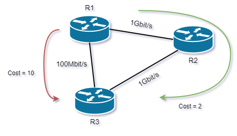
Each link between routers is assigned a metric known as the "cost" or "path cost." OSPF calculates the shortest path by summing the costs of all the links along the path.

Formula
Cost = Reference Bandwidth / Interface Bandwidth

The Reference Bandwidth is a configurable value in OSPF and is set to 100 Mbps by default. For this example, it has been configured to 1000 Mbps manually.

1Gbit/s Link
100Mbit/s Link
Cost = 1000 Mbps / 1000 Mbps
Cost = 1000 Mbps / 100 Mbps
Cost = 1
Cost = 10

The path cost is determined by the bandwidth of the link. The higher the bandwidth, the lower the cost. For example, a fast Ethernet link may have a cost of 10 while a gigabit Ethernet link may have a cost of 1. The lowest cost path is always preferred.
Administrative Distance

Administrative Distance (AD) is a value that is used to rate the priority of different routing protocols. AD is used by routers to determine which routing protocol should be preferred if multiple routing protocols are providing routing information for the same destination network. The router compares the AD of each routing protocol and selects the route with the lowest AD value as the best path.

Protocol
RIP - Routing Information Protocol
EIGRP - Enhanced Interior Gateway Routing Protocol
OSPF - Open Shortest Path First
IS-IS - Itermediate System Intermediate System
IBGP - Internal Border Gateway Protocol
BGP - Border Gateway Protocol
Static route
Directly connected interface
Method
Hop Count - Distance Vector
Bandwith & Delay
Bandwith & Link State
Link State
Path Vector
Path Vector
Manually configured route
Directly connected interface
Protocol Type
IGP - Interior Gateway Protocol
EGP - Exterior Gateway Protocol
Manual route
Directly connected interface
Administrative Distance
120
90
110
115
200
20
1
0

Premium Access

Log in or register - Premium members can access all content without restrictions.

Get Premium

0 Comments

Submit a Comment