Introduction
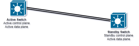
Stackwise Virtual is a technology developed by Cisco that allows to combine two physical switches and become a single logical switch. From a physical point of view there are two separate devices, from a logical point of view it is a device consisting of two stack members. This technology connects multiple switches together and an administrator can manage them as a single unit. Traditionally, Cisco switches have been stacked physically using the Stackwise technology. However, Stackwise Virtual creates a logical switch using two physical switches that are connected via their uplink interfaces. The logical switch created by Stackwise Virtual acts as a single device and provides benefits such as simplified management, increased scalability, and reduced downtime. Both devices actively forward traffic, regardless of who currently has the active role, In contrast to First Hop Redundancy Protocols, the standby node is not entirely passive. All switch ports on both devices can actively forward traffic at the same time. Therefore, the bandwidth is doubled and the device management is limited to the active device. The active device has the active control plane. Only one IP address is needed to manage both devices.

Advantages
The administration is easier, because it is no longer necessary to manage 2 systems separately, as it is the case with First Hop Redundancy Protocols. If one of them fails, there is no major interruption of the data connection. The bandwidth is halved because the interfaces of the standby device remain active. The standby member only has to take over the control of the system and become the active member, which has no effect on the traffic. The manual configuration of virtual gateway adresses is no longer necessary. Since both participants are constantly synchronized via the Stackwise-Virtual links, both have all the necessary information at all times to immediately take over the active role and also the active data connections, should the active member fail. Devices configured with a First Hop Redundancy Protocol must first reestablish all connections, and the data traffic will only continue after the standby device takes over the active role. The SVL failover process is not noticeable during operation, but the failover process of FHRP devices is noticeable throughout the site because the currently inactive device first has to start forwarding packets again.
Preparation
At the beginning, the same software version must be installed on both devices. Stackwise Virtual cannot be started with devices that have different software versions installed. The “show version” command displays the current software version. The command "show boot" displays the BOOT variables. Both devices should have "bootflash:packages.conf" as BOOT variable. After that, inter-connect both devices via multiple uplink ports with each other. These connections will be used for Stackwise-Virtual.

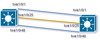
Connect the switch port interfaces to each other to establish layer 2 connectivity. The command “show cdp neighbors” and “show interface status” will tell if the connections are ready for further configuraiton. At least 10 Gigabit links should be used for the inter-connections between both devices. For this example the interfaces 1/0/1, 1/0/25, 1/0/48 and six 10 Gigabit SFPs have been used.
show boot
SW1#show boot
BOOT variable = bootflash:packages.conf;
MANUAL_BOOT variable = no
BAUD variable = 9600
ENABLE_BREAK variable does not exist
BOOTMODE variable does not exist
IPXE_TIMEOUT variable does not exist
CONFIG_FILE variable =
SW1#


SW2#show boot
BOOT variable = bootflash:packages.conf;
MANUAL_BOOT variable = no
BAUD variable = 9600
ENABLE_BREAK variable does not exist
BOOTMODE variable does not exist
IPXE_TIMEOUT variable does not exist
CONFIG_FILE variable =
SW2#
show version
SW1#show version
Cisco IOS XE Software, Version 17.03.06
Cisco IOS Software [Bengaluru], Catalyst L3 Switch Software (CAT9K_IOSXE), Version 17.3.6, RELEASE SOFTWARE (fc2)
Technical Support: http://www.cisco.com/techsupport
Copyright (c) 1986-2023 by Cisco Systems, Inc.
Compiled Wed 25-Jan-23 16:15 by mcpre


Cisco IOS-XE software, Copyright (c) 2005-2023 by cisco Systems, Inc.
All rights reserved.  Certain components of Cisco IOS-XE software are
licensed under the GNU General Public License ("GPL") Version 2.0.  The
software code licensed under GPL Version 2.0 is free software that comes
with ABSOLUTELY NO WARRANTY.  You can redistribute and/or modify such
GPL code under the terms of GPL Version 2.0.  For more details, see the
documentation or "License Notice" file accompanying the IOS-XE software,
or the applicable URL provided on the flyer accompanying the IOS-XE
software.


ROM: IOS-XE ROMMON
BOOTLDR: System Bootstrap, Version 17.3.1r, RELEASE SOFTWARE (P)

Switch uptime is 4 minutes
Uptime for this control processor is 5 minutes
System returned to ROM by Reload Command
System image file is "bootflash:packages.conf"
Last reload reason: Reload Command


This product contains cryptographic features and is subject to United
States and local country laws governing import, export, transfer and
use. Delivery of Cisco cryptographic products does not imply
third-party authority to import, export, distribute or use encryption.
Importers, exporters, distributors and users are responsible for
compliance with U.S. and local country laws. By using this product you
agree to comply with applicable laws and regulations. If you are unable
to comply with U.S. and local laws, return this product immediately.

A summary of U.S. laws governing Cisco cryptographic products may be found at:
http://www.cisco.com/wwl/export/crypto/tool/stqrg.html

If you require further assistance please contact us by sending email to
export@cisco.com.


Technology Package License Information:

------------------------------------------------------------------------------
Technology-package                                     Technology-package
Current                        Type                       Next reboot
------------------------------------------------------------------------------
network-advantage   	Smart License                 	 network-advantage
dna-advantage       	Subscription Smart License    	 dna-advantage
AIR License Level: AIR DNA Advantage
Next reload AIR license Level: AIR DNA Advantage


Smart Licensing Status: Registration Not Applicable/Not Applicable

cisco C9500-48Y4C (X86) processor with 2889884K/6147K bytes of memory.
Processor board ID CAT2338L0UX
1 Virtual Ethernet interface
48 TwentyFive Gigabit Ethernet interfaces
4 Hundred Gigabit Ethernet interfaces
32768K bytes of non-volatile configuration memory.
15995680K bytes of physical memory.
11161600K bytes of Bootflash at bootflash:.
1638400K bytes of Crash Files at crashinfo:.

Base Ethernet MAC Address          : 00:00:00:00:00:01
Motherboard Assembly Number        : XXXX
Motherboard Serial Number          : XXXXXXX
Model Revision Number              : XXX
Motherboard Revision Number        : X
Model Number                       : C9500-48Y4C
System Serial Number               : XXXXXXX

SW1#


SW2#show version
Cisco IOS XE Software, Version 17.03.06
Cisco IOS Software [Bengaluru], Catalyst L3 Switch Software (CAT9K_IOSXE), Version 17.3.6, RELEASE SOFTWARE (fc2)
Technical Support: http://www.cisco.com/techsupport
Copyright (c) 1986-2023 by Cisco Systems, Inc.
Compiled Wed 25-Jan-23 16:15 by mcpre


Cisco IOS-XE software, Copyright (c) 2005-2023 by cisco Systems, Inc.
All rights reserved.  Certain components of Cisco IOS-XE software are
licensed under the GNU General Public License ("GPL") Version 2.0.  The
software code licensed under GPL Version 2.0 is free software that comes
with ABSOLUTELY NO WARRANTY.  You can redistribute and/or modify such
GPL code under the terms of GPL Version 2.0.  For more details, see the
documentation or "License Notice" file accompanying the IOS-XE software,
or the applicable URL provided on the flyer accompanying the IOS-XE
software.


ROM: IOS-XE ROMMON
BOOTLDR: System Bootstrap, Version 17.3.1r, RELEASE SOFTWARE (P)

Switch uptime is 4 minutes
Uptime for this control processor is 5 minutes
System returned to ROM by Reload Command
System image file is "bootflash:packages.conf"
Last reload reason: Reload Command


This product contains cryptographic features and is subject to United
States and local country laws governing import, export, transfer and
use. Delivery of Cisco cryptographic products does not imply
third-party authority to import, export, distribute or use encryption.
Importers, exporters, distributors and users are responsible for
compliance with U.S. and local country laws. By using this product you
agree to comply with applicable laws and regulations. If you are unable
to comply with U.S. and local laws, return this product immediately.

A summary of U.S. laws governing Cisco cryptographic products may be found at:
http://www.cisco.com/wwl/export/crypto/tool/stqrg.html

If you require further assistance please contact us by sending email to
export@cisco.com.


Technology Package License Information:

------------------------------------------------------------------------------
Technology-package                                     Technology-package
Current                        Type                       Next reboot
------------------------------------------------------------------------------
network-advantage   	Smart License                 	 network-advantage
dna-advantage       	Subscription Smart License    	 dna-advantage
AIR License Level: AIR DNA Advantage
Next reload AIR license Level: AIR DNA Advantage


Smart Licensing Status: Registration Not Applicable/Not Applicable

cisco C9500-48Y4C (X86) processor with 2889884K/6147K bytes of memory.
Processor board ID CAT2338L0UX
1 Virtual Ethernet interface
48 TwentyFive Gigabit Ethernet interfaces
4 Hundred Gigabit Ethernet interfaces
32768K bytes of non-volatile configuration memory.
15995680K bytes of physical memory.
11161600K bytes of Bootflash at bootflash:.
1638400K bytes of Crash Files at crashinfo:.

Base Ethernet MAC Address          : 00:00:00:00:00:02
Motherboard Assembly Number        : XXXX
Motherboard Serial Number          : XXXXXXX
Model Revision Number              : XXX
Motherboard Revision Number        : X
Model Number                       : C9500-48Y4C
System Serial Number               : XXXXXXX

SW2#
show cdp neighbor
SW1#show cdp neighbor
Capability Codes: R - Router, T - Trans Bridge, B - Source Route Bridge
                  S - Switch, H - Host, I - IGMP, r - Repeater, P - Phone,
                  D - Remote, C - CVTA, M - Two-port Mac Relay

Device ID        Local Intrfce     Holdtme    Capability  Platform  Port ID
SW2              Twe 1/0/25        175             R S I  C9500-48Y Twe 1/0/25
SW2              Twe 1/0/1         170             R S I  C9500-48Y Twe 1/0/1
SW2              Twe 1/0/48        157             R S I  C9500-48Y Twe 1/0/48

Total cdp entries displayed : 3
SW1#


SW2#show cdp neighbor
Capability Codes: R - Router, T - Trans Bridge, B - Source Route Bridge
                  S - Switch, H - Host, I - IGMP, r - Repeater, P - Phone,
                  D - Remote, C - CVTA, M - Two-port Mac Relay

Device ID        Local Intrfce     Holdtme    Capability  Platform  Port ID
SW1              Twe 1/0/25        175             R S I  C9500-48Y Twe 1/0/25
SW1              Twe 1/0/1         170             R S I  C9500-48Y Twe 1/0/1
SW1              Twe 1/0/48        157             R S I  C9500-48Y Twe 1/0/48

Total cdp entries displayed : 3
SW2#

0 Comments